Creating a TrueNAS CORE cluster
Introduction
This document describes how to create a highly available clustered TrueNAS system using RSF-1 software. The base system should consist of two nodes running the latest release of TrueNAS CORE, with external storage connected to both nodes concurrently (commonly referred to as shared storage) or a pool replicated on a remote node (shared-nothing).
Features
- ZFS pools created on the shared storage can be failed over between cluster nodes - these are referred to as shared pools.
- RSF-1 is an Active-Active cluster. This means a pool can be active on, and failover to, any node in the cluster.
- Multiple pools can be clustered with no interdependencies; meaning you could have two pools on one node and three on another and then fail over all pools from the first to the second, or just one from the second to the first etc.
- A shared pool can only be imported on any one cluster node at a time. RSF-1 uses disk reservations to enforce this rule to protect data.
- Any services configured to use a shared pool (such as NFS/SMB) are accessible on the node the pool is imported on.
- Multiple heartbeats over network and disk for shared-storage (no dedicated heartbeat drive required - integrates with existing ZFS drives with no reconfiguration required)
The TrueNAS System Dataset Pool
TrueNAS saves system configuration information in the System
Dataset Pool - usually the first ZFS pool created on the system.
The effect of this means that the pool containing that dataset
is not eligible for clustering (as the pool containing the system
dataset cannot be exported, and attempts to do so will result in
failure with a 'unmount failed' message).
The solution to this is to move the location of the system dataset to
the boot pool (or a pool not being considered for clustering).
This is done in the GUI by navigating to ** System -> System Dataset **,
selecting the boot pool from the drop down list of pools and finally
saving the change.
For a highly-available system we would recommend each cluster node
has a dedicated boot drive, mirrored if possible1.
Note
When the boot pool is the only imported pool, TrueNAS will
always show this as the location of the system dataset. This
configuration however is not permanent until it is actually
saved. Failure to do so leaves TrueNAS open to the possibility
of relocating the system dataset, which can cause issues in the
cluster (as outlined above). The rule here is, even if TrueNAS reports
the system dataset as residing on the boot pool, make sure that
setting is saved, thereby making it a permanent feature
(this need only be done once on each cluster node).

Accessing cluster services over the network
With a non clustered storage appliance, services such as NFS, SMB etc.
are accessed using the IP address of the storage appliance itself. For
clustered systems this causes an issue in that when the pool, and by
implication any services reliant on that pool, is migrated to
another node, those services become inaccessible using the original storage
appliances IP address (as it no longer hosts those services).
RSF-1 solves this problem by associating
a Virtual IP address (VIP) with a pool, and by implicaition any
services using the pool. The VIP is then migrated with the pool should
a fail over occur. Clients then access storage services using the VIPs
configured rather than the static IP address of the node itself. This
approach means that clients need not be aware of where a highly
available service is running, or indeed need reconfiguration when a
failover occurs, safe in the knowledge that the VIP will always point
to the location of the services in the cluster.
When configuring a VIP in the cluster, either an IP address or a hostname
can be used. When using a hostname the cluster needs to resolve this to an
IP address. iTo ensure that this resolution is not dependent on external
naming services RSF-1 automatically adds VIP's to the TrueNAS Host Name
Database.
Installation and configuration
Perform steps 1-5 on both nodes in the cluster:
- Allow the RSF-1 package to be installed by enabling the FreeBSD
repository and disabling the local one. This is only a temporary
change which will revert back to the default settings next time the
system is rebooted (done as part of this installation).
Start a command shell using the **>_ Shell** menu item in the TrueNAS GUI and edit the file/usr/local/etc/pkg/repos/FreeBSD.confand set the FreeBSD enabled value to yes: Next edit the file/usr/local/etc/pkg/repos/local.confand set the enabled value to no: - Browse to the RSF-1 Offline Package Repo and find the latest version
for your version of TrueNAS CORE. Once the correct package is located download
it and the associated signature using wget:
Calculate the checksum of the downloaded RSF-1 package and ensure it matches the checksum held in the
# wget https://packages2.high-availability.com/offline-packages/TrueNAS-CORE/13.0-U5.3/rsf-1-1.11-TN-13.0-U5.3.pkg # wget https://packages2.high-availability.com/offline-packages/TrueNAS-CORE/13.0-U5.3/rsf-1-1.11-TN-13.0-U5.3.pkg.sha512sha512file (the output of thesha512andcatcommands should be the same): Once the checksum has been verified, install the RSF-1 package: -
Enable automatic start of the RSF-1 system. This is done by running the provided init script in
/opt/HAC/bin. This will add init scripts to TrueNAS:errors when running truenas-init.sh
When running the
/opt/HAC/bin/truenas-init.shscript, it may fail with an error:This is due to python 3.12 enforcing new ssl specifications, which are only present in newer sqlite versions. This can be resolved by updating sqlite3 from the FreeBSD repo. To do this, ensure the changes from step 1 are applied (these changes will disappear when TrueNAS CORE is rebooted) and run the command# /opt/HAC/bin/truenas-init.sh Traceback (most recent call last): File "TrueNAS/initcommands.py", line 1, in <module> import sqlite3 File "/opt/HAC/Python/lib/python3.12/sqlite3/__init__.py", line 57, in <module> from sqlite3.dbapi2 import * File "/opt/HAC/Python/lib/python3.12/sqlite3/dbapi2.py", line 27, in <module> from _sqlite3 import * ImportError: /opt/HAC/Python/lib/python3.12/lib-dynload/_sqlite3.cpython-312.so: Undefined symbol "sqlite3_deserialize"pkg install -y sqlite3 -
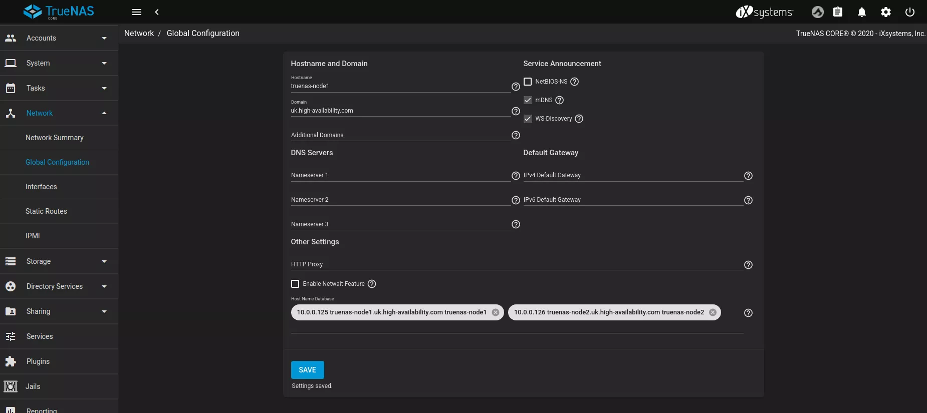
In the GUI navigate to **
Here is an example configuration with two static entries in the hosts file:Network -> Global Configuration** and update the TrueNAS host name database with static entries for the cluster nodes. This step is essential so host name lookup is not reliant on any external services that could potentially fail. Each node should have entries for all cluster nodes in the host name database using the format:
- Finally, reboot the node.
Configure pools and create cluster
-
If you haven't already created your cluster storage pool(s), do so now on one of the cluster nodes via the TrueNAS GUI. This must be done using only drives from the shared storage3.
Shared Nothing
If creating a shared nothing cluster a pool will need to be created on both nodes with the same name in the TrueNAS GUI. Step 2 below is not required
-
Once you have a pool eligible for clustering it is necessary to make other cluster nodes "aware" of that pool for failover. This is accomplished in two steps:
-
In a shell on node 2 run
glabel refreshon each of the disks in the pool to ensure the gptid's created by TrueNAS are matching on both nodes. This can also help the second node detect the pool. For example:# for i in {1..19}; do; glabel refresh da$i; done Metadata from da1 refreshed. Metadata from da2 refreshed. Metadata from da3 refreshed. Metadata from da4 refreshed. Metadata from da5 refreshed. Metadata from da6 refreshed. Metadata from da7 refreshed. Metadata from da8 refreshed. Metadata from da9 refreshed. Metadata from da10 refreshed. Metadata from da11 refreshed. Metadata from da12 refreshed. Metadata from da13 refreshed. Metadata from da14 refreshed. Metadata from da15 refreshed. Metadata from da16 refreshed. Metadata from da17 refreshed. Metadata from da18 refreshed. Metadata from da19 refreshed. -
Check the pool is visible by running
zpool import, then by checking the output against the commandzpool statuson node-1 you can confirm the gptid's match on both machines:node-2# zpool import pool: pool1 id: 1093288960321296894 state: ONLINE action: The pool can be imported using its name or numeric identifier. config: pool1 ONLINE raidz3-0 ONLINE gptid/923587e1-78d8-11ee-b18a-3daea9f4e77b ONLINE gptid/921f40f7-78d8-11ee-b18a-3daea9f4e77b ONLINE gptid/925493e5-78d8-11ee-b18a-3daea9f4e77b ONLINE gptid/9227da0b-78d8-11ee-b18a-3daea9f4e77b ONLINE gptid/924e32b1-78d8-11ee-b18a-3daea9f4e77b ONLINE gptid/92288c6d-78d8-11ee-b18a-3daea9f4e77b ONLINE gptid/9217ead1-78d8-11ee-b18a-3daea9f4e77b ONLINE gptid/92272408-78d8-11ee-b18a-3daea9f4e77b ONLINE gptid/91fbc95e-78d8-11ee-b18a-3daea9f4e77b ONLINE gptid/92188c29-78d8-11ee-b18a-3daea9f4e77b ONLINE gptid/923443fa-78d8-11ee-b18a-3daea9f4e77b ONLINE gptid/9253dcdc-78d8-11ee-b18a-3daea9f4e77b ONLINE gptid/9241a769-78d8-11ee-b18a-3daea9f4e77b ONLINE gptid/92339ba1-78d8-11ee-b18a-3daea9f4e77b ONLINE gptid/922935a7-78d8-11ee-b18a-3daea9f4e77b ONLINE gptid/9234e0c5-78d8-11ee-b18a-3daea9f4e77b ONLINE gptid/948cdf41-78d8-11ee-b18a-3daea9f4e77b ONLINE gptid/9490720c-78d8-11ee-b18a-3daea9f4e77b ONLINE gptid/94961bc0-78d8-11ee-b18a-3daea9f4e77b ONLINE gptid/948fc902-78d8-11ee-b18a-3daea9f4e77b ONLINEnode-1# zpool status pool1 pool: pool1 state: ONLINE config: NAME STATE READ WRITE CKSUM pool1 ONLINE 0 0 0 raidz3-0 ONLINE 0 0 0 gptid/923587e1-78d8-11ee-b18a-3daea9f4e77b ONLINE 0 0 0 gptid/921f40f7-78d8-11ee-b18a-3daea9f4e77b ONLINE 0 0 0 gptid/925493e5-78d8-11ee-b18a-3daea9f4e77b ONLINE 0 0 0 gptid/9227da0b-78d8-11ee-b18a-3daea9f4e77b ONLINE 0 0 0 gptid/924e32b1-78d8-11ee-b18a-3daea9f4e77b ONLINE 0 0 0 gptid/92288c6d-78d8-11ee-b18a-3daea9f4e77b ONLINE 0 0 0 gptid/9217ead1-78d8-11ee-b18a-3daea9f4e77b ONLINE 0 0 0 gptid/92272408-78d8-11ee-b18a-3daea9f4e77b ONLINE 0 0 0 gptid/91fbc95e-78d8-11ee-b18a-3daea9f4e77b ONLINE 0 0 0 gptid/92188c29-78d8-11ee-b18a-3daea9f4e77b ONLINE 0 0 0 gptid/923443fa-78d8-11ee-b18a-3daea9f4e77b ONLINE 0 0 0 gptid/9253dcdc-78d8-11ee-b18a-3daea9f4e77b ONLINE 0 0 0 gptid/9241a769-78d8-11ee-b18a-3daea9f4e77b ONLINE 0 0 0 gptid/92339ba1-78d8-11ee-b18a-3daea9f4e77b ONLINE 0 0 0 gptid/922935a7-78d8-11ee-b18a-3daea9f4e77b ONLINE 0 0 0 gptid/9234e0c5-78d8-11ee-b18a-3daea9f4e77b ONLINE 0 0 0 gptid/948cdf41-78d8-11ee-b18a-3daea9f4e77b ONLINE 0 0 0 gptid/9490720c-78d8-11ee-b18a-3daea9f4e77b ONLINE 0 0 0 gptid/94961bc0-78d8-11ee-b18a-3daea9f4e77b ONLINE 0 0 0 gptid/948fc902-78d8-11ee-b18a-3daea9f4e77b ONLINE 0 0 0 errors: No known data errors
-
-
Finally, navigate to the RSF-1 secure web interface running on port 8330 on the node where the shared pool is imported5 to complete the cluster configuration.
Configuration and Licensing
To begin configuration, click on Create/Destroy option on the
side-menu (or the shortcut on the panel shown when first logging in).
The Cluster Create page scans for clusterable nodes (those running
RSF-1 that are not yet part of a cluster)
and presents them for selection:
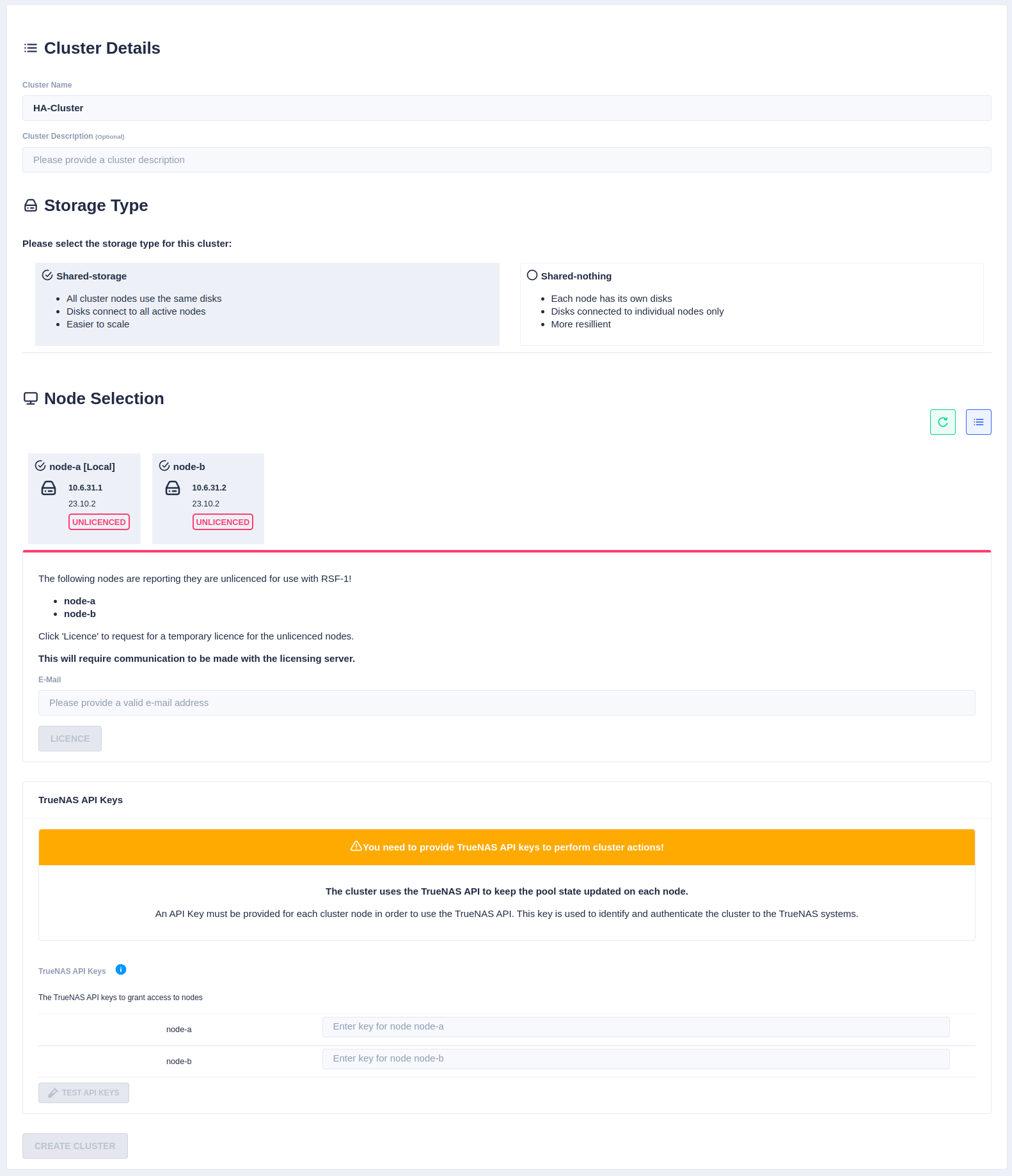
Now enter the cluster name and description, and then
select the type of cluster being created (either shared-storage or
shared-nothing).
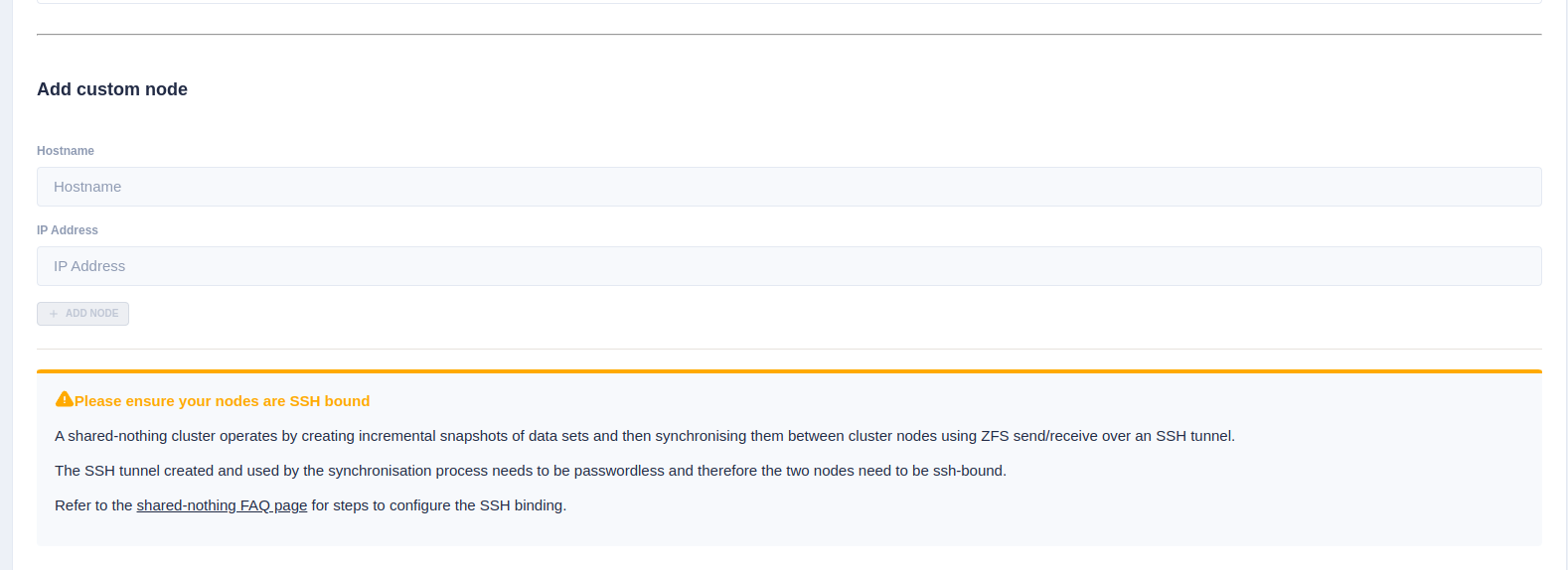
If setting up a shared-nothing cluster an additional option to add a
node manually is shown at the bottom of the page. This is because
RSF-1 will detect nodes on the local network, but for shared-nothing
clusters, the partner node could be on a separate
network/location, and therefore may not automatically be detected1.
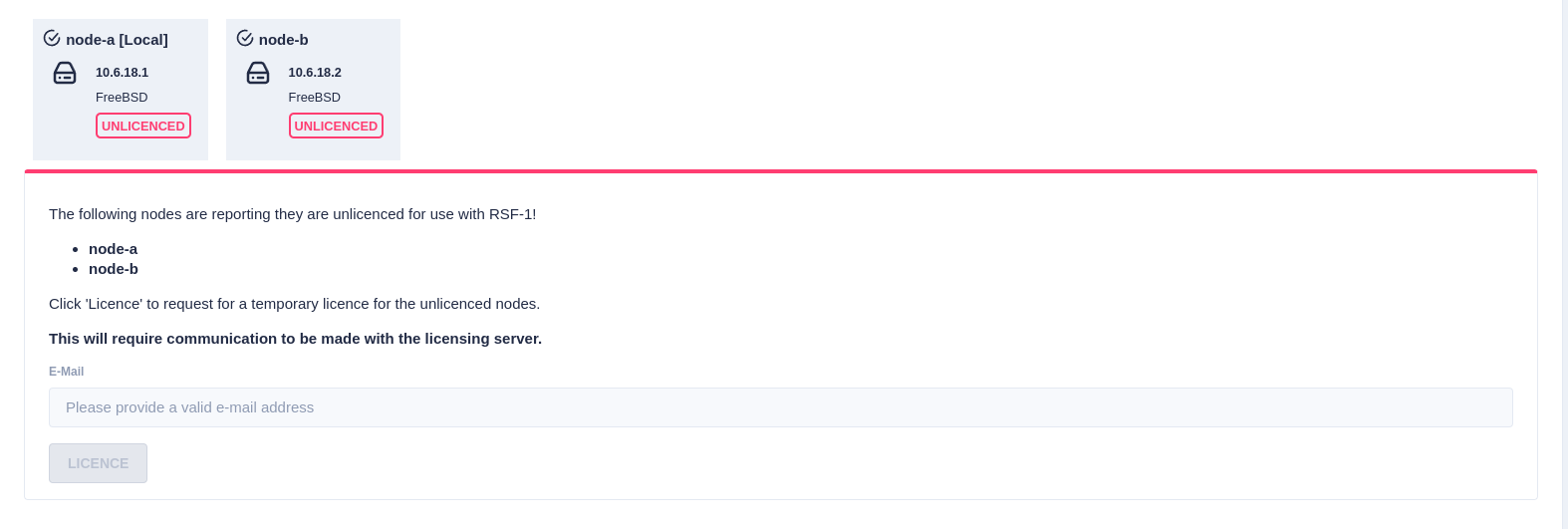
Trial Licenses
If any of the selected nodes have not been licensed,
a panel is shown to obtain 45 day trial licenses:
Next, the RSF-1 End User License Agreement (EULA) will
be displayed. Click accept to proceed:

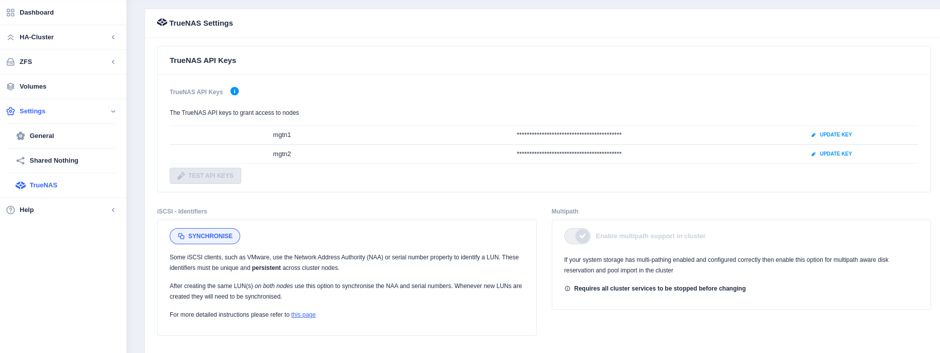
API Keys
As of version 1.11, RSF-1 requires API Keys to interact with TrueNAS to import/export pools. These can be created in the TrueNAS GUI.
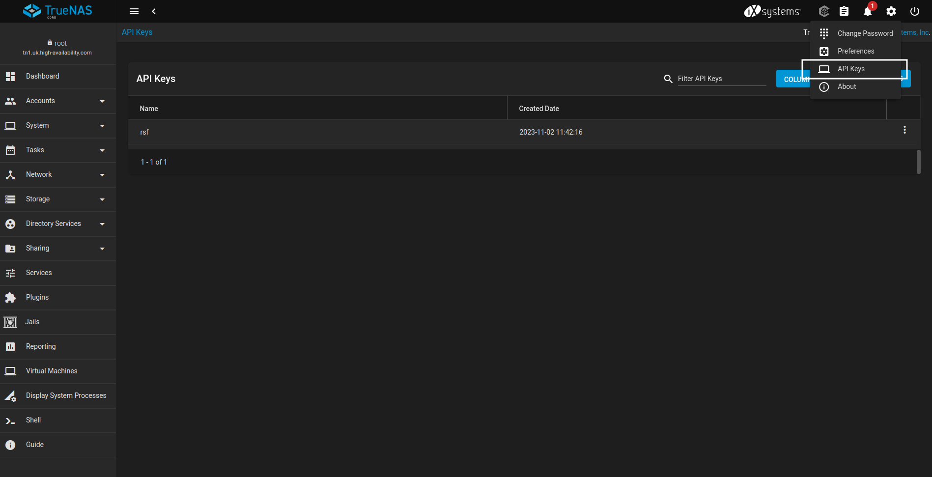
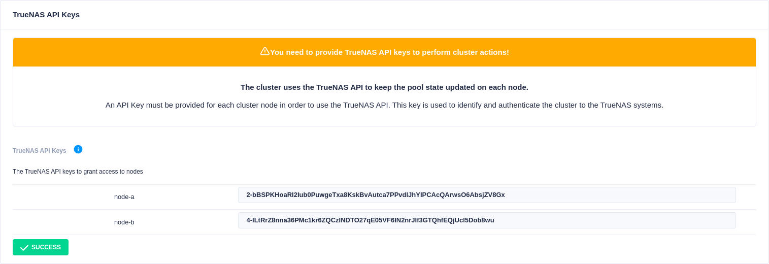
As each key is created add it to the RSF-1 API keys field for each node.
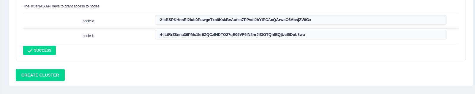
Once created in TrueNAS add them in the API Keys section and click TEST API KEYS
which will confirm the keys are valid
Finally click the Create Cluster button to initialize the cluster:
When the cluster has been created, you can enable support for disk multipathing in RSF-1 if the disks have already been configured:
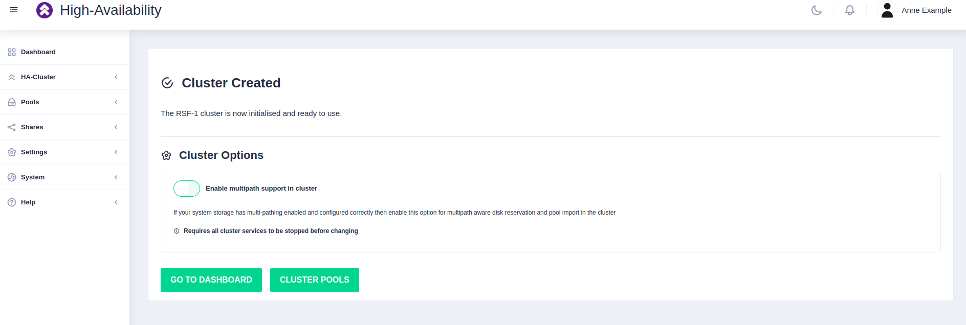
This setting can be modified after cluster set-up if needed.
It can be found in Settings -> TrueNAS.
Enabling Multipath Support
If the nodes have been configured to use disk multipathing you must enable multipath support otherwise disk reservations will not function correctly. Do not enable if disks are configured for singlepath only.
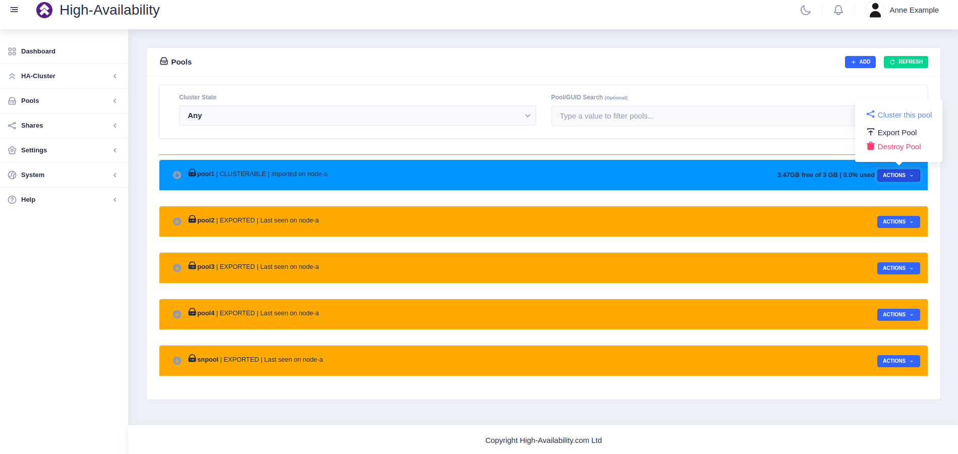
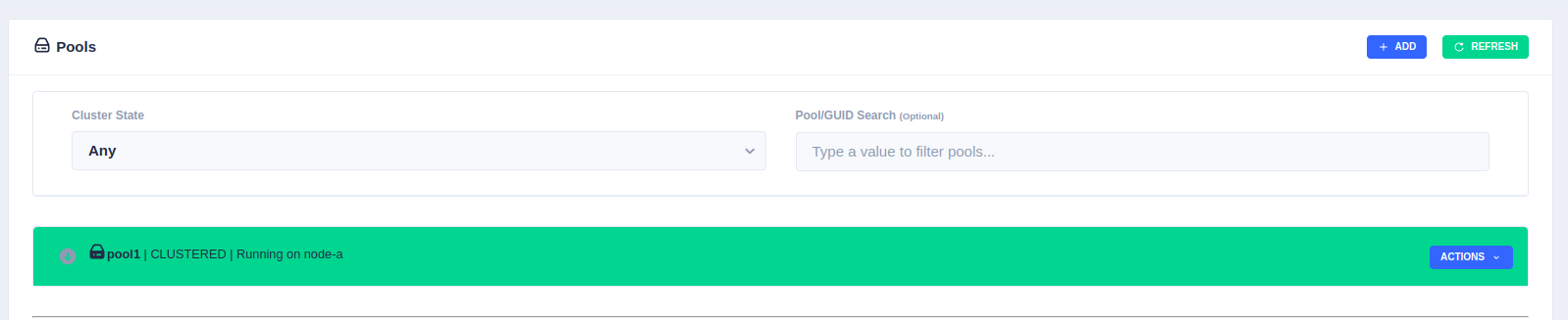
Clustering a Pool
Highlight the desired pool
to be clustered (choose only pools marked CLUSTERABLE ), then select Actions
followed by Cluster this pool:
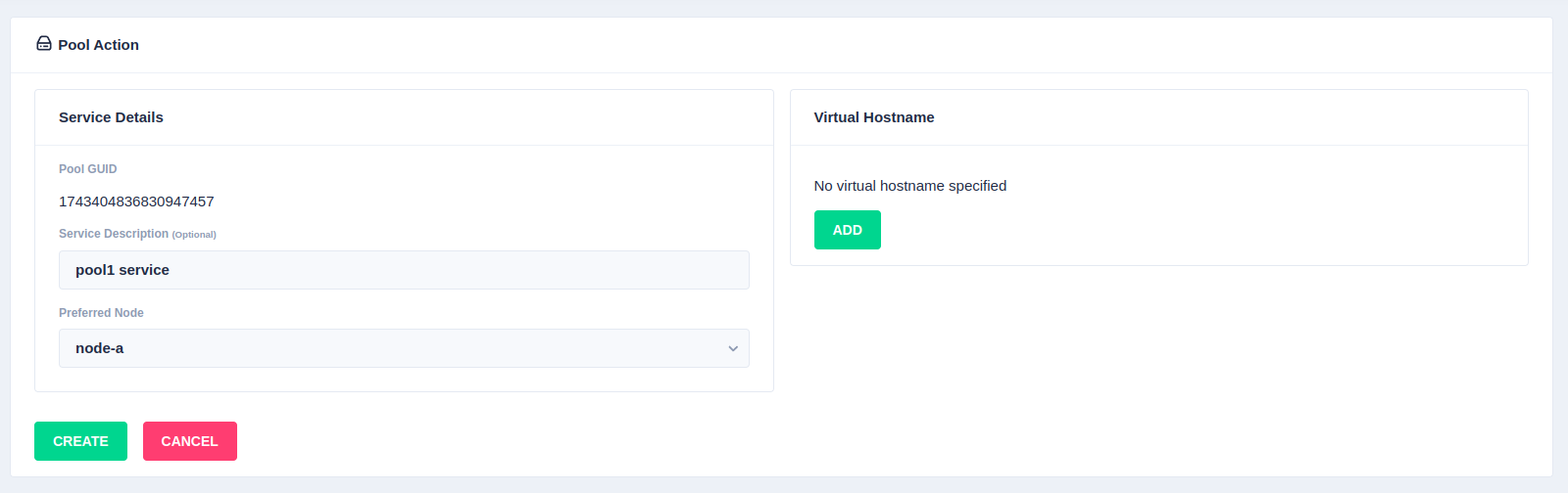
Fill out the description and select the preferred node for the service:
What is a preferred node
When a service is started, RSF-1 will initially attempt to run it on it's preferred node. Should that node be unavailable (node is down, service is in manual etc) then the service will be started on the next available node.
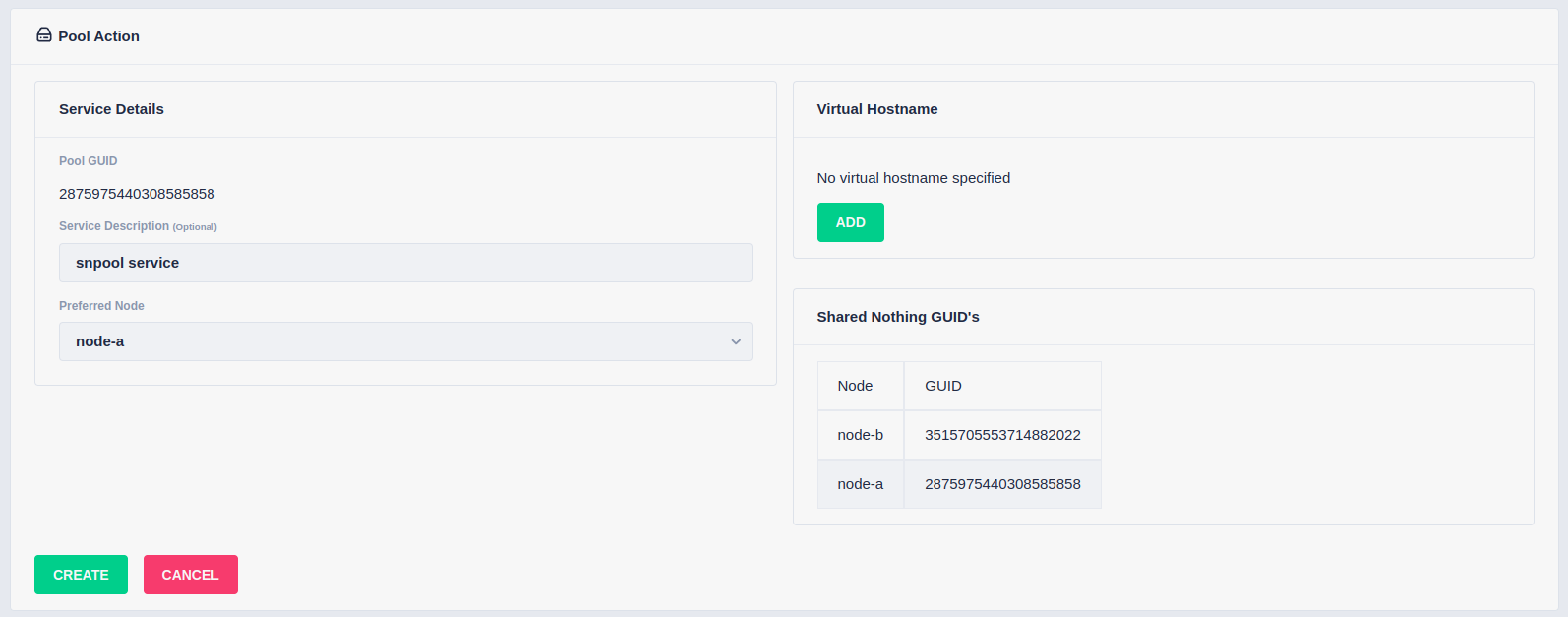
With a shared-nothing pool the GUID's for each pool will be shown:
To add a virtual hostname to the service click Add in the Virtual
Hostname panel. Enter the IP address, and optionally a hostname, in the
popup. For nodes with multiple network interfaces, use the drop down
lists to select which interface the virtual hostname should be assigned
to. Click the next button to continue:
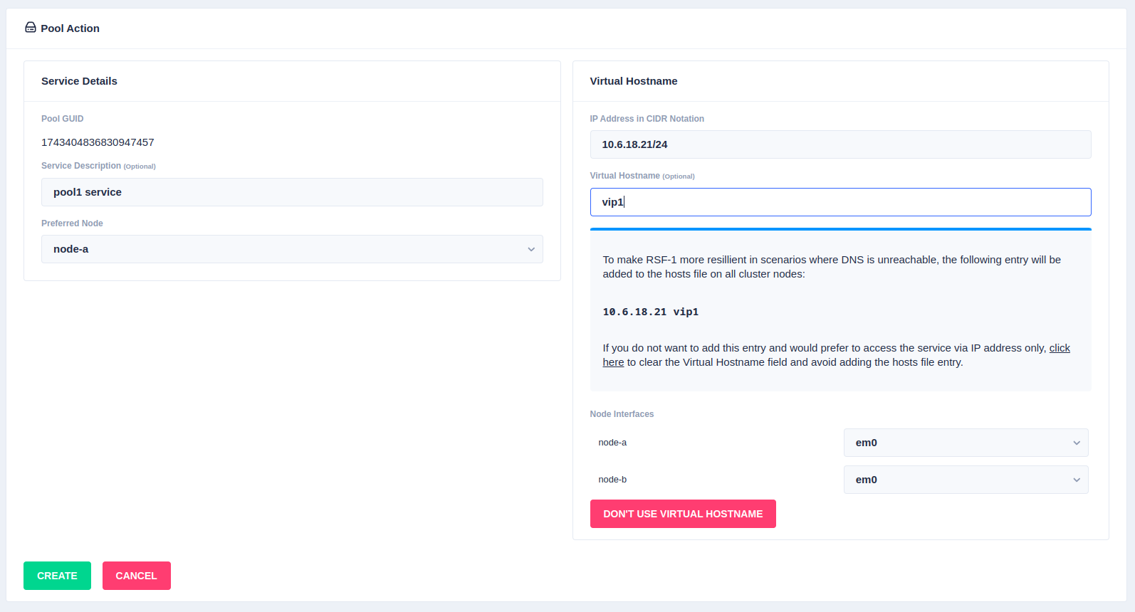
Finally, click the Create button:

The pool will now show as CLUSTERED:
Setting up shares on clustered pools
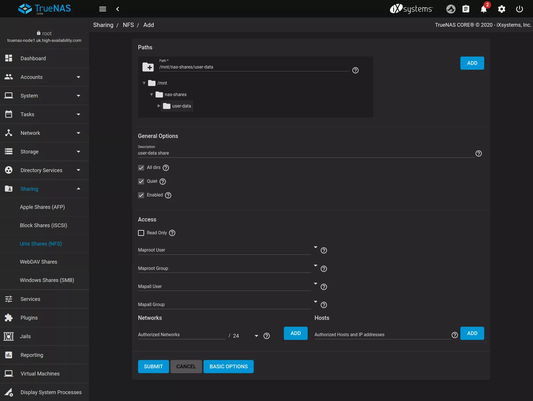
TrueNAS uses a local configuration to save details of shares created for a pool (NFS, SMB etc). When a pool in a cluster fails over from one node to another that share information is not migrated with the pool. For this reason, when setting up a new share on a clustered pool, it is necessary to duplicate the share configuration on each node in the cluster.
For example, in a cluster with two nodes, Node-A and Node-B,
with clustered pool nas-shares, to share
/mnt/nas-shares/user-data via NFS the following steps are required:
- Start the service configured with the
nas-sharespool onNode-A. - Add the NFS share:
- Fail over the service to
Node-B. - Again add the NFS share using the same parameters as were used
on
Node-A.
Note - this configuration step needs only be done once on the cluster for each share (but will need to be repeated for each additional share).
Setting up iSCSI share on clustered pools
As with NFS and SMB shares, TrueNAS uses a local configuration to save details of iSCSI shares created for a pool, and thus any new iSCSI share created requires it's config to be duplicated on each node in the cluster.
For example, in a cluster with two nodes, Node-A and Node-B,
to create an iSCSI share:
-
On
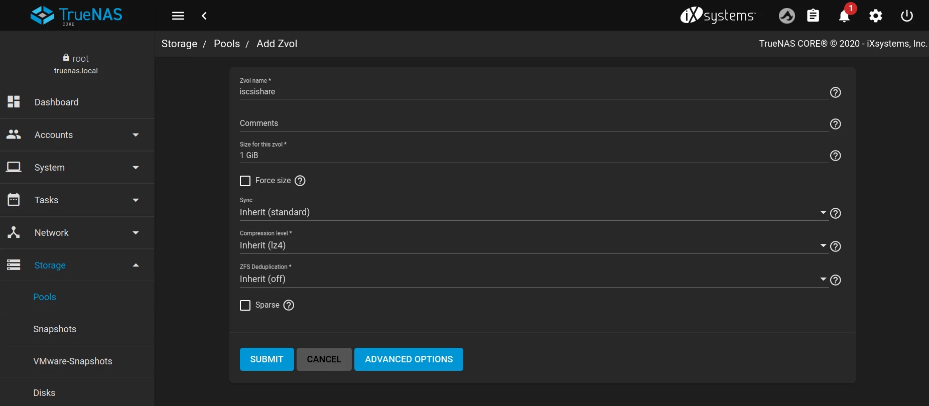
Node-A, start the service you want to create iSCSI shares on. -
Navigate to
Storage -> Poolsand create a Zvol; in this example we have created a 1GB zvol callediscsishareusing default options.
-
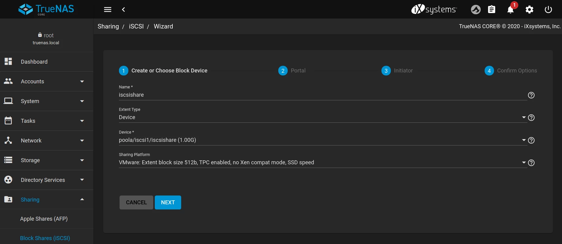
Navigate to
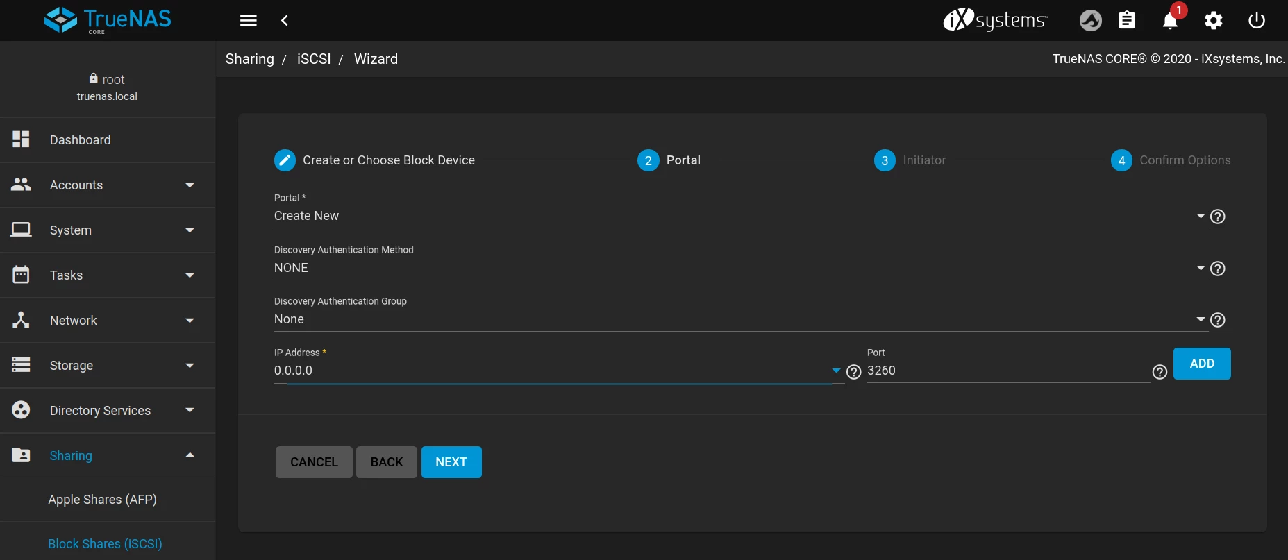
Sharing -> Block Shares (iSCSI)and create an iSCSI share using the wizard:
-
In step 2 (Portal), make sure the IP address entered is 0.0.0.0 (this is so it can be accessed using the cluster VIP that moves with the service in the event of a failover).
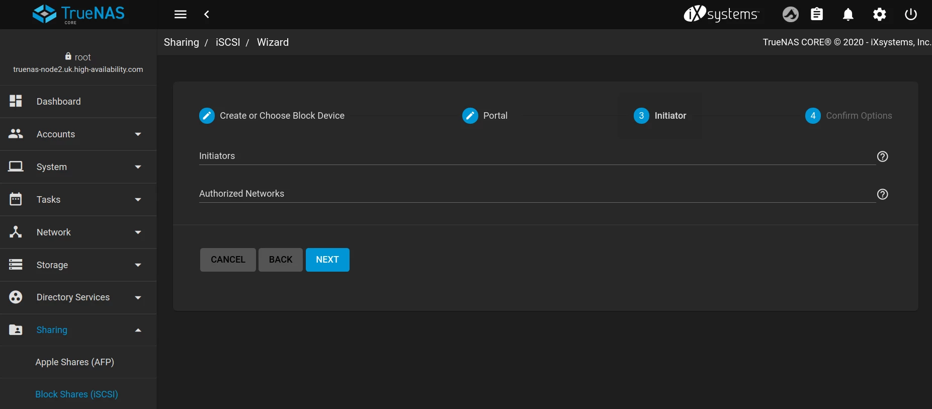
-
If desired, provide initiators/authorized networks in the next step (in this example it's been left blank so any client/network can connect to the target):
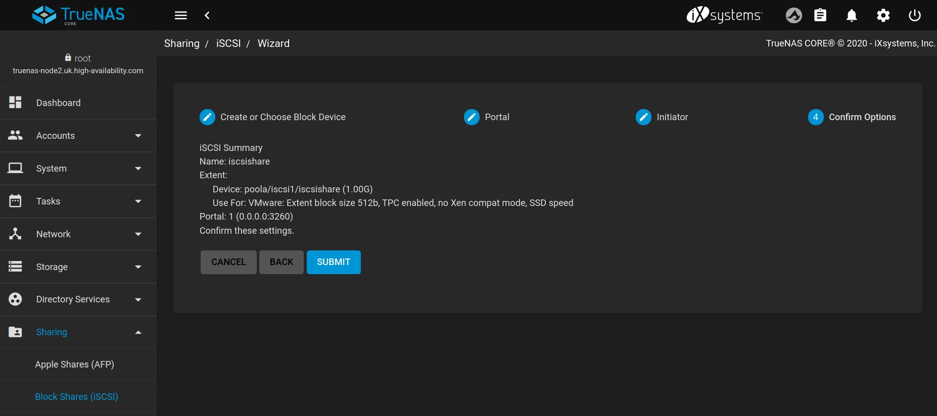
-
Finally confirm the iSCSI target creation by clicking
SUBMIT:
-
Now move the service over to
Node-B, and re-create the iSCSI share using the same perameters as used onNode-A -
Your iSCSI share should now be discoverable via the VIP (in this example the service VIP is
10.0.0.127)6:
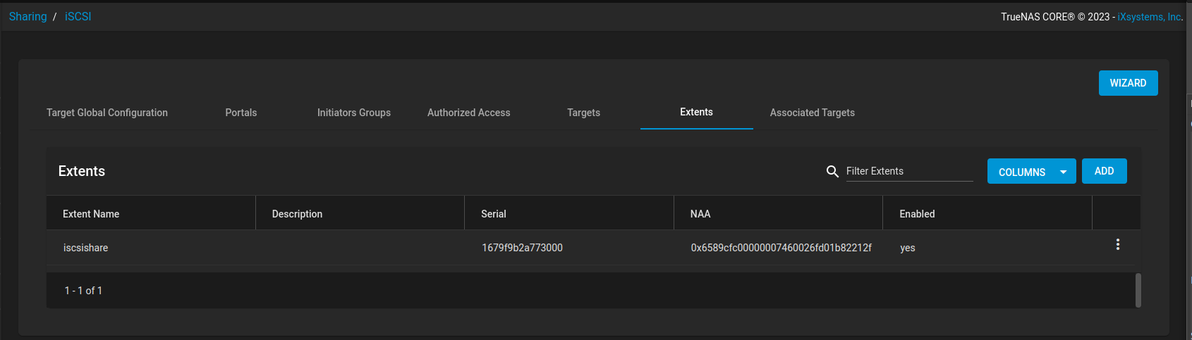
Synchronising iSCSI NAA identifiers across cluster nodes
Available in RSF-1 version 2.1+
Some iSCSI clients use identifiers to uniquely identify devices. They are based on specific storage standards in one of the following formats:
- eui.xxx
- naa.xxx
- t10.xxx
Whenever an iSCSI Extent is created, TrueNAS automatically generates and assignes a unique serial number and NAA. In a clustered environment both these fields must be the same on each node for a specific extent, so that on pool failover clients are presented with the same identifiers for uninterrupted operation. However, as each iSCSI extent is created in isolation on each cluster node, initially the serial number and NAA will be different.
In the following example the extent iscsishare has been created on both cluster nodes and, as can be seen,
each node has a different serial number and NAA:
Node 1
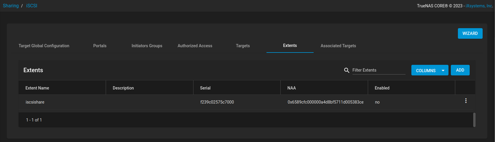 Node 2
In order to synchronise these fields across cluster nodes navigate to Settings -> TrueNAS in the RSF-1 webapp
and click the SYNCHRONISE button to replicate the identifiers to all cluster nodes:
Note
- It is necessary to synchronise identifiers every time new extents are created.
- Synchronisation can be run on any node, as often as required.
-
Startup/running performance can also be improved by using SSD or NVMe disks as the boot drive(s). ↩↩
-
Because if this service is unavailable when the cluster tries to resolve the hostname then service startup cannot continue in a normal fashion. ↩
-
If any drives in a clustered pool are local to a node, i.e. do not reside in the shared storage, then this will result in a failure to import on any other cluster node as that local drive will be inaccessible. For this reason it is mandatory that all cluster drives reside in shared storage. ↩
-
Use the GUI **
>_ Shell** menu item to access the cli. ↩ -
If the pool is imported on say
truenas-node2then the URL ishttps://truenas-node2:4330. ↩ -
TrueNAS uses the default global IQN of
iqn.2005-10.org.freenas.ctlsuffixed with the name of the share. ↩