Configuration
What are the different cluster timeouts used for?
RSF-1 uses a number of timeouts to manage service startup. These timeouts are:
- Initial timeout - used when a cluster node first boots up.
- Heartbeat timeout - used to trigger heartbeat failure detection.
- Run timeout - used on service startup.
The following sections describe each of these timeouts in detail.
Initial Timeout
One of the first operations a cluster node performs during its start up process (i.e. when it is first powered on) is to gather information about the services configured in the cluster and, upon finding any eligible services1 not running, start them.
This approach however introduces a slight race condition,
typically triggered when more than one cluster node starts
up at the same time (for example in the case of a power outage
and subsequent restoration).
To understand how this condition manifests itself,
consider the following scenario in a two node
cluster, Node-A and Node-B, with a single service Service-1, who's
preferred node is Node-A:
- Both nodes are powered up at the same time.
Node-Bcompletes booting ahead ofNode-Aand starts gathering service infomation.- Because
Node-Ahas not yet completed booting,Node-BseesService-1as down with no other nodes available to run the service. Node-Bstarts the service.
As as result Service-1 is started, but not on its preferred node.
This is what the initial timeout value addresses - it is a time in seconds
that each node should wait once booted, but before attempting to
start services. This allows some leeway for other cluster nodes to
complete their boot process before service startup decisions are made.
In the above example, should Node-A have completed booting in
the initial timeout period then, when Node-B came to make any service
start decisions, it would see Node-A was available and of a higher priority
for the service and therefore allow the service to start on the that node.
The default value for the initial timeout is 20 seconds. This value will always be a balance of what is a reasonable amount of time to wait for all cluster node to starts vs. what is an acceptable time to defer service startup waiting for other cluster nodes.
Heartbeat Timeout
Nodes in a cluster communicate with each other using heartbeats. A cluster node sends heartbeats to all other nodes in the cluster at a regular beat rate,2 and should in turn receive heartbeats from all peers in the cluster at the same rate. Heartbeats serve two important functions:
- They let other nodes in the cluster know the sending node is up and running.
- They communicate important state information about cluster services.
The information contained within a heartbeat is then used to update the internal state held for the sending node, which, most importantly, includes the last time the remote node was seen (and therefore considered up). The heartbeat timeout is then used in conjunction with the last time a nodes state was updated to decide when that node is considered down.3
Once all heartbeats are down for a node, then any services that node was running are eligible for starting in the cluster - however, before starting any services, a secondary timeout has to occur, this is known as the run timeout.
Run timeout
The run timeout setting is used to assist cluster node coordination during a service startup. Its usage is slightly different depending on if it is a two node or greater than two node cluster.
The minimum value for the run timeout is two seconds. This limit is imposed to provide sufficient time for state information to percolate to all nodes in the cluster after taking into account possible synchronicity delays in disk heartbeats (as they have to be polled every second, unlike network heartbeats which are event driven).
Two node cluster
With a two node cluster there are four possible scenarios why a service startup on a node occurs:
- The service is stopped and in
manualmode on all cluster nodes. The service is then transitioned toautomaticin the cluster. The highest priority machine for the service should then immediatly attempt to start the service. The secondary node waits for the run timeout to expire before considering if it should start the service. Under normal circumstances the service will start on the primary node and the secondary will do nothing. If however the service fails to start on the primary node, then, once the run timeout expires on the secondary node, it will detect the service has not started and attempt to start it itself. - The node running the service fails. In this case the run timeout is ignored and the remaining node (if eligible) will attempt to start the service once the heartbeat timeout has expired.
- A move service command is issued. In this case the run timeout is ignored.
- One node halts the service due to a resource failure (for example the network monitor has detected a failure on one of the VIP interfaces). In this case the run timeout is ignored and the other node starts the service if eligible.
Two+ node cluster
When there are more than two nodes in a cluster then the rules governing the use of the run timeout apply to only the nodes eligible to run a specific service. Furthermore, where a service is bound to two nodes only, then the two node cluster rules above apply.
When a service can potentially run on more than two nodes then the above rules apply along with an additional rule:
- In the case where more than one node is eligible to run a service
then the highest priority node for that service will take over (once the
run timeout is honoured). Any
other, less eligible, servers will defer to that server (i.e. will not attempt
to start the service).
There is however one corner case where the run timeout is used to arbitrate between eligible servers where the most eligible is inmanualmode and the next in line is inautomatic. In this scenario the node in automatic will wait for the run timeout to expire and, if the other higher priority node is still inmanual, attempt to start the service. In the mean time if the other server is set toautomatic, then it will also honour the run timeout, giving it enough time to see that the service is now being started on another, lower priority, node, thus avoiding any potential race condition.
What is the difference between a machine name and a host name?
Every machine in an RSF cluster needs a unique and unchanging machine name for RSF-1 to associate with it. This is normally the same as the host name, but must be different if the host name changes as part of a service fail over (or the host name doesn't resolve to a valid IP address).
The machine names used by RSF-1 are the names which appears in MACHINE lines in the config file. These names are normally associated with real machines by checking to see that they match the host name of that machine. However if a host ID appears on a MACHINE line, then the host name check is not done, and the association is made by checking the host ID (as returned by hac_hostid) instead. Note that in this case the IP address of the machine MUST be specified on the end of the line, as it is assumed that the machine name is not the same as the host name, and thus can't be used to look up the IP address of the host.
This flexible naming scheme also allows multiple hosts in a cluster to have the same host name (a requirement seen in a few applications).
To specify the optional host ID of the machine on the MACHINE line preceded it by "0x" (to indicate it is a hexadecimal value). RSF-1 will then identify that machine by the name on the MACHINE line, even if it does not match the real host name. Here is an example MACHINE entry with corresponding host ID:
MACHINE slug 0x2ae5747
RSF also sets the environment variable RSF_MACHINE_NAME in any service startup/shutdown scripts to the machine name in use. This allows scripts to create log messages using the same machine name as rsfmon itself.
Machine names are also used on heartbeat (NET, DISK and SERIAL) lines to indicate what machine the heartbeat is being sent to, and on SERVER lines to indicate which machines may act as act as a server for a service.
Escape syntax when the machine name / vip starts with a number
In the case where the machine name starts with a number or contains special characters, a specific syntax is required when using the name in a rsfcdb command or updating the config file.
For example, if 0-node1 and 0-node2 are the machine names, then, when using the rsfcdb to build the database, the machine name must be preceded by the percent symbol, i.e. %0-node1, therefore to establish a network heartbeat between the two nodes 0-node1 and 0-node2, the command to use is:
rsfcdb ha_net %0-node1#0-node2 0-node2#0-node1
Escape syntax for VIP's
VIP's with special characters are handled slightly differently and should be enclosed in double quotes.
For example, if the vip name we would like to use is 0-testvip1, then to add that VIP to a service named zpool1 the command is:
rsfcdb sa_desc zpool1#"0-testvip1" "RSF-1 zpool1 ZFS service"
Which will result in a configuration file entry similar to:
# Machines section
MACHINE %0-node1
NET %0-node2
DISC %0-node2 /dev/rdsk/c15t2d0s0:512:518
SERVICE tank1 "0-viptest1" "RSF-1 zpool1 ZFS service"
Do I need to use dedicated disks for heartbeats or reservations?
An RSF-1 cluster uses shared disks for both heartbeats and disk fencing.
Disk Heartbeats
When a disk is used for heartbeats, RSF-1 on each cluster node will use a small portion of the disk to regularly write information about the state of the cluster according to that node. That information will then be read by the remote node and used to build up a picture of the whole cluster.
For a ZFS cluster, disk heartbeats are not required to be dedicated disks. RSF-1 understands the layout of ZFS pool drives and is able to place heartbeat information on any pool disk without disrupting either user data or ZFS metadata.
Disk fencing
When a disk is used by RSF-1 for the purposes of fencing a SCSI reservation is placed on that disk during the startup sequence of a HA service. The reservations are placed before the ZFS pool is imported with the purpose to prevent other cluster nodes from writing to the pool after it is locally imported. This is important for any situation where a cluster node appears to go offline - prompting a service failover to the remaining node - but in reality that node is still running and accessing the pool. In that case, the SCSI reservations will block access to the pool from the failing node, allowing the remaining node to safely take over.
Reservation drive selection is handled automatically by recent versions of the RSF-1 cluster but for older, manually configured versions or for any situations where the cluster configuration must be changed from the default settings, there are three important requirements for the selection of reservation drives:
-
Because the reservations are used to fence the ZFS pool's disks, it must be the pool's disks that are reserved - so dedicated disks should not be used for reservations. Additionally, it should be regular data disks that are reserved. SCSI reservations on disks marked as "cache" (L2ARC) or "spare" will not have any effect on the ability of another node to access the pool and will therefore not contribute towards adequate data protection.
By default, the cluster will also avoid using disks marked as "log" (SLOG). This is less important from a data protection perspective but it has been found that since the purpose of a separate log device is to provide a performance improvement, the type of disk devices used for log tend to be more "cutting edge" than regular data disks and are more likely to exhibit unexpected behaviour in response to SCSI reservations. -
Reservation disks should be selected in such a way that the reservations would prevent pool access from the remote node. For example, if a pool is made up of several 4-way mirrors, then as a minimum, reservations should be placed on all 4 devices in any one mirror vdev. This would mean the entire vdev will be inaccessible to the remote node and therefore, the whole pool will be inaccessible.
-
Reservations cannot be placed on the same disks as heartbeats. Depending on the type of reservations used by the cluster the reservation will block either reads and writes, or just writes, from one of the cluster nodes. Because each disk heartbeat requires both nodes to be able to read and write to the disk, reservations and disk heartbeats will conflict and result in the disk heartbeat being marked down while the service is running on either node.
What disk layout should I use for my ZFS HA pool and how does this impact reservations and heartbeat drives?
For ZFS file systems there are essentially two main approaches in use, RAID Z2 and a mirrored stripe. To give a brief overview of these two schemes lets see how they layout when we have six drives, 1TB each (note that within any pool, any drives used for reservations or to heartbeat through are still usable for data, i.e. NO dedicated drives are required; the cluster software happily co-exists with ZFS pools).
RAID Z2
Raid Z2 uses two parity drives and at least two data drives, so the minimum amount of drives is four. With six 1TB drives this then equates to the following layout with roughly 4TB of usable space (parity drives highlighted in green):
D1 |
D2 |
D3 |
D4 |
P1 |
P2 |
With this configuration up to two drives (parity or data) can be lost and pool integrity still maintained; any more drive losses though will result in the pool becoming faulted (essentially unreadable/unimportable).
In order to place reservations on this drive layout it is necessary to reserve three drives (say P1, P2, D1) - in this way no other node will be able to successfully import the pool as there are not enough unreserved drives to read valid data from.
With resertions in place on drives P1, P2 and D1, this leaves drives D2, D3 and D4 free to use for disk heartbeats. The RSF-1 cluster software is aware of the on-disk ZFS structure and is able to heartbeat through the drives without affecting pool integrity.
RAID 10
Raid 10 is a combination of mirroring and striping; firstly mirrored vdevs are created (RAID 1) then striped together (RAID 0). With six drives we have a choice on the mirror layout depending on the amount of redundancy desired. These two schemas can be visualised as follows, firstly two three way mirrors striped together:
D0 |
D3 |
|
D1 |
D4 |
|
D2 |
D5 |
|
| vdev1 | + | vdev2 |
In this example two mirrors have been created (D0/D1/D2 and D3/D4/D5) giving a total capacity of 2TB. This layout allows a maximum of two drives to fail in any single vdev (for example D0 and D2 in vdev1, D0 and D3 in vdev 1 and 2, etc.); the pool could survive four drive failures as long as a single drive is left in vdev1 and vdev2, but if all fail in one side of the stripe (for example D3, D4 and D5) then the pool would fault.
The reservations for this layout would be placed on all drives in either vdev1 or vdev2, leaving three drives free for heartbeats.
Alternatively the drives could be layed out as three two way mirrors striped together:
D0 |
D2 |
D4 |
||
D1 |
D3 |
D5 |
||
| vdev1 | + | vdev2 | + | vdev3 |
In this example three mirrors have been created (D0/D1, D2/D3 and D4/D5) giving a total capacity of 3TB, with a maximum of one drive failure in any single vdev. Reservations will be placed on either vdev1, vdev2 or vdev3 leaving four drives available for heartbeating.
In all of the above scenarios it is NOT necessary to configure reservations or heartbeats; when a pool is added to a cluster, the cluster software will interrogate the pool structure and automatically work out the amount of drives it needs to reserve with any remaining drives utilised for heartbeats. Note that for each clustered pool only a maximum of two heartbeat drives are configured (any more is overkill).
RSF-1 network ports and firewalls
The following network ports are used by the cluster software:
1195(TCP/UDP) used for low level interprocess communications and to handle requests from the RESTapi4330(TCP) used by the RESTapi process to service REST calls (including those from the WEB app) and to communicate with RSF-1 on port11958330(TCP) the port the WEB application listens on
Firewall considerations:
- Access to ports
1195and4330is only required between cluster nodes. - Port
8330needs to be accessible if you wish to access the web app from non cluster machines.
Configuring additional network heartbeats
The standard process for creating a network heartbeat is:
- Plumb in the addresses on the interfaces for the additional heartbeat
- Add the address to
/etc/hostswith a hostname - the new addresses need to be added to both nodes - Create the heartbeats for both directions via the webgui using the new hostnames
In this example there is a new IP on each of the nodes, mgomni1 has mgomnihb1 with address 192.168.16.1, and mgomni2 has mgomnihb2 with address 192.168.16.2, here's what /etc/hosts looks on both machines, and their interfaces:
# Host table
::1 localhost
127.0.0.1 localhost loghost
10.6.16.1 mgomni1
10.6.16.2 mgomni2
192.168.16.1 mgomnihb1
192.168.16.2 mgomnihb2

root@mgomni1:~# ipadm show-addr
ADDROBJ           TYPE     STATE        ADDR
lo0/v4            static   ok           127.0.0.1/8
vmxnet3s0/dhcp    dhcp     ok           10.6.16.1/8
vmxnet3s1/hb      static   ok           192.168.16.1/24
lo0/v6            static   ok           ::1/128

root@mgomni2:~# ipadm show-addr
ADDROBJ           TYPE     STATE        ADDR
lo0/v4            static   ok           127.0.0.1/8
vmxnet3s0/dhcp    dhcp     ok           10.6.16.2/8
vmxnet3s1/hb      static   ok           192.168.16.2/24
lo0/v6            static   ok           ::1/128
Then, in the webapp, create the additional heartbeat as below:
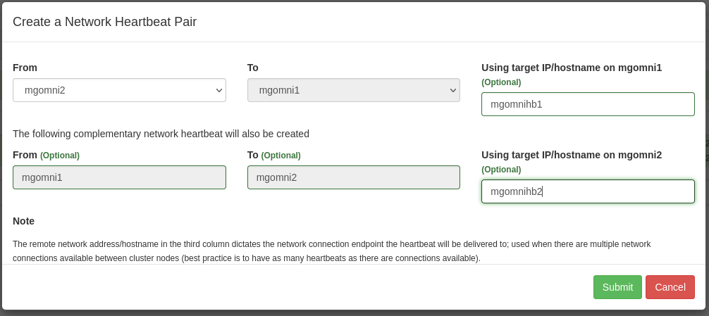
From mgomni2 to mgomni1, the target ip/hostname would be mgomnihb1, and for mgomni1 to mgomni2 the target would be mgomnihb2.